Well over a year ago, I blogged about starting a project in which I replace a radio-controlled car’s guts with an Arduino and have it be able to navigate to a given GPS location.
Well, that project is finally underway.
Hardware
It very quickly became apparent that an Arduino wouldn’t cut it for the kind of computational work I want to do, mainly because of the tiny amount of RAM it has. I ended up with a pairing of a Raspberry Pi and an Arduino Uno. The Arduino’s job is to interface with the various sensors on the car and pass that information back to the Pi, which has a lot more resources for doing computation.
Note: This chapter is a fairly quick overview of how the car is put together. You can find a shopping list with exact components at the end of this post.
Arduino
The Arduino has a prototype board attached to it, which on the underside has two three-pin connectors for connecting the car’s servos (one for speed, one for steering). The car’s speed controller is connected to the battery and provides the Arduino with power.
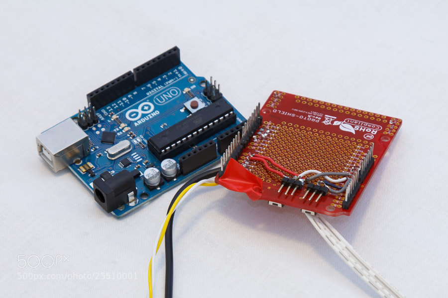
The top of the board (which is very messy — I intend to build a much neater one) hosts an accelerometer as well as a few cables for powering the Raspberry Pi, powering the Ultrasonic Sensors and reading data from the Ultrasonic sensors.
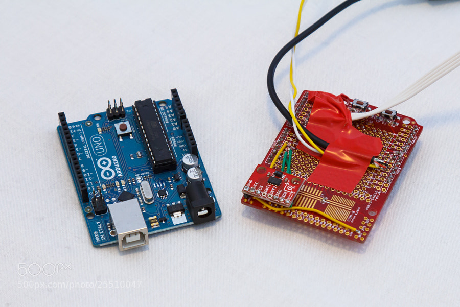
Black: Raspberry Pi power, Yellow and white: Ultrasonic sensor power, White four-lane: Ultrasonic sensor data, Raised red board: Accelerometer.
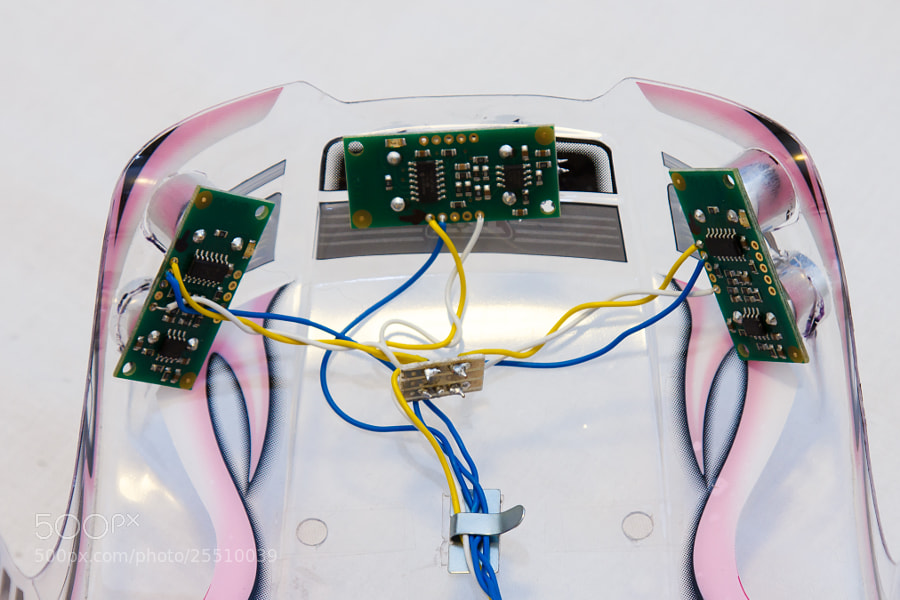
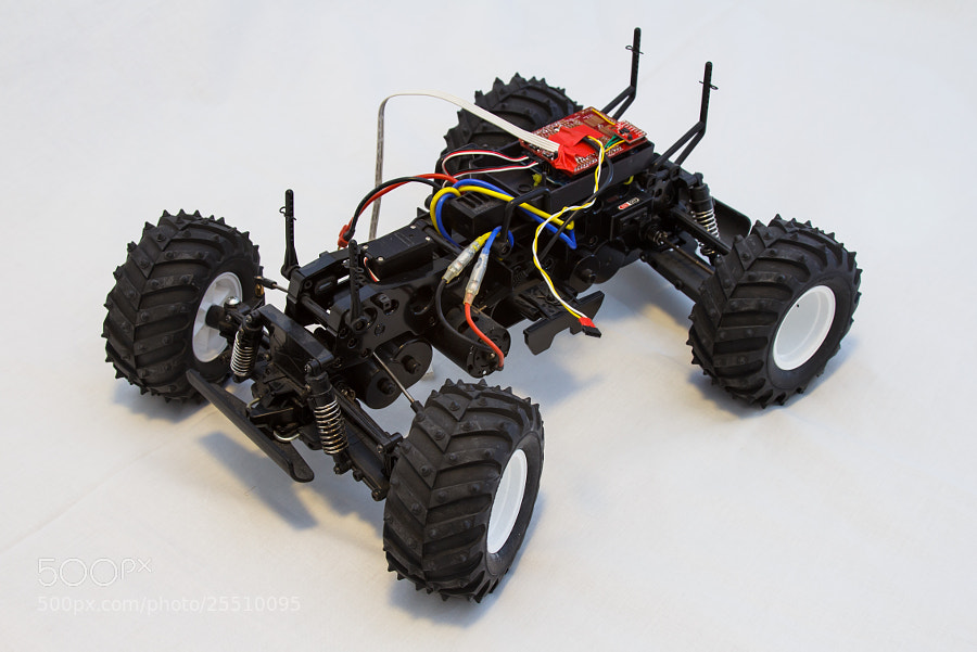
There are four Ultrasonic sensors mounted on the car’s body — three at the front and one at the rear. All the cabling for these sensors end up at a pair of connectors on the inside of the roof, which allows the body to easily be separated from the chassis when needed.
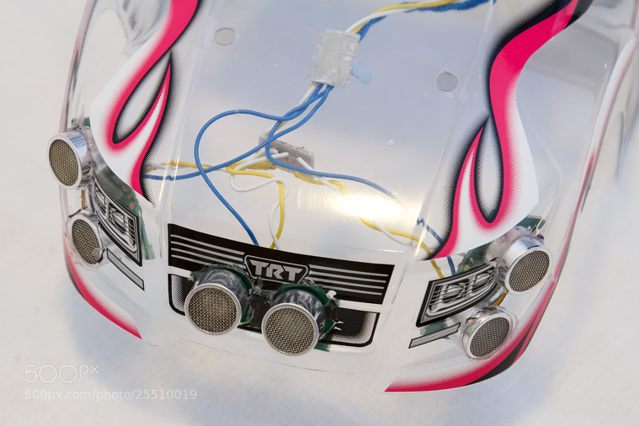
Leaving the body clear so you could see the electronics seemed like a good idea at the time, but instead it all looks messy and is really hard to photograph. Lesson learned!
The Arduino and prototype board are mounted inside an Arduino case that’s attached to the car’s chassis with zip ties. The case has a lid, but I’ve left it out of the photos to illustrate what goes there.
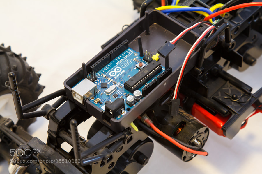
The vertical posts support the body, which rests on the clips. They can be raised to give more room.
Raspberry Pi
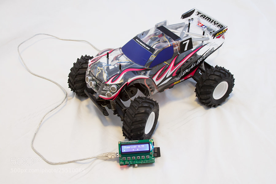
The Raspberry Pi is mated with a UI module from BitWizard, which hosts a 2x16 character LCD display, six buttons and a few breakout connectors for various serial busses.
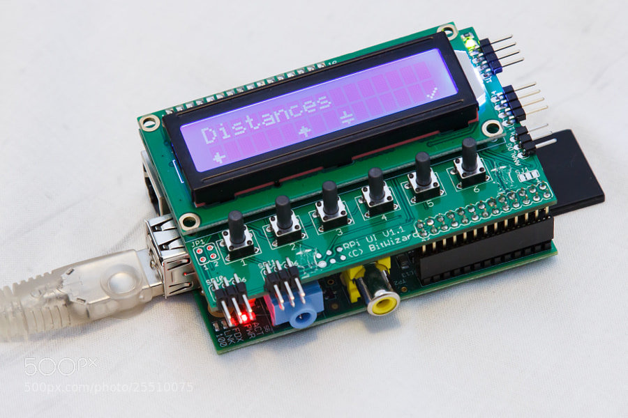
Raspberry Pi with attached UI module. The garbled character to the right of the up arrow should be a down arrow, but there seems to be a bug in my custom character code!
The Raspberry Pi connects to the Arduino twice — once for power from the Arduino and once via USB to communicate with it. When it’s all assembled, it gets rather messy!
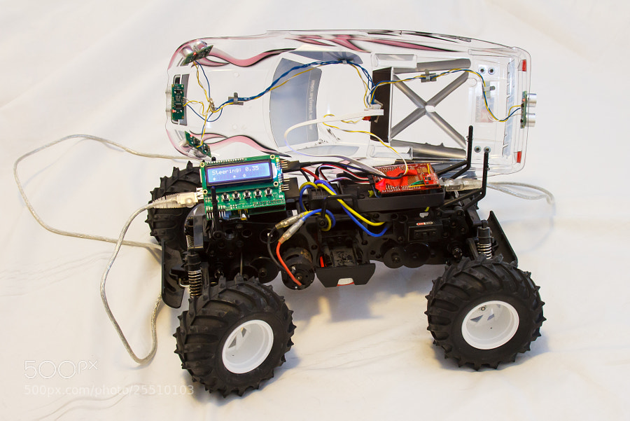
Thankfully, with the body on, it’s a lot cleaner. The final part is to find a housing for the Raspberry Pi and a place to mount it on the car itself.
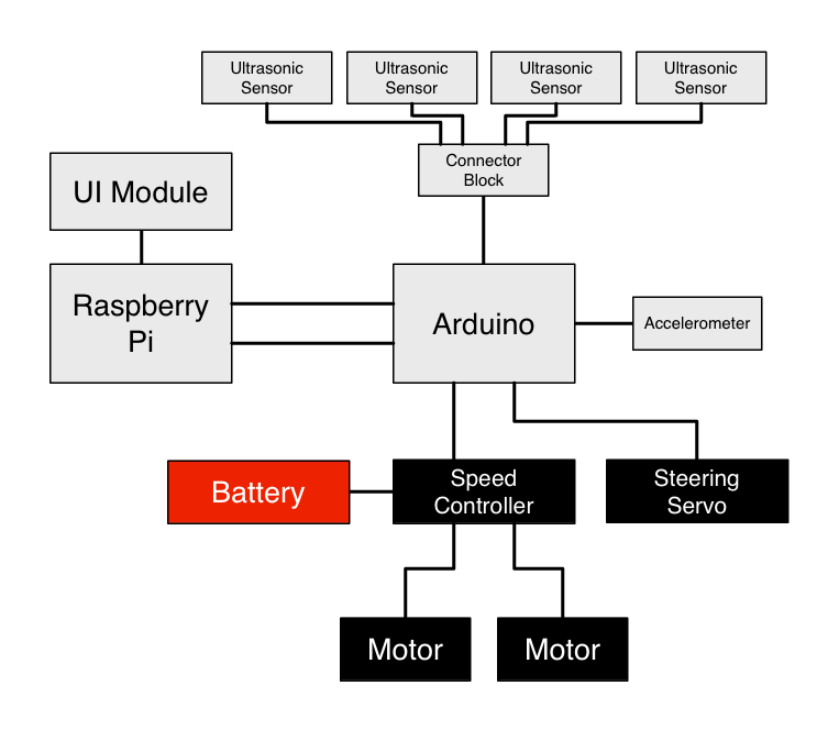
Here’s a diagram of how everything fits together. Clear as mud!
Software
Arduino
The Arduino is running a very simple loop that polls the attached sensors and writes their values out to the serial port. ACCEL: lines are accelerometer readings in G, and DISTANCE: lines are ultrasonic sensor readings in cm.
ACCEL: 0.06,0.05,0.89
ACCEL: 0.07,0.05,0.90
ACCEL: 0.07,0.05,0.90
ACCEL: 0.06,0.05,0.90
ACCEL: 0.06,0.05,0.88
DISTANCE: 89,111,32,15
ACCEL: 0.07,0.05,0.89
ACCEL: 0.07,0.05,0.90
ACCEL: 0.07,0.04,0.90
ACCEL: 0.07,0.05,0.90
ACCEL: 0.07,0.06,0.90
DISTANCE: 89,111,32,15
Sample Arduino output.
In addition, the Arduino listens for input on the serial port for setting speed and steering values for the servos. This is not unlike the protocol used in my Arduino LED project, with two header bytes, a byte for the steering angle (0 - 180), a byte for the throttle angle (0 - 180) and a checksum byte.
Main Software Stack - Raspberry Pi
Everything so far is just enabling the main software stack of the car to observe and interact with the hardware in the car.
The main software stack is written in C# against the Mono Framework. I chose this setup because it’s pretty much the only nice Object-Oriented language available with a fully featured runtime available on multiple platforms (of course, there’s also Python and Java, but I prefer C# over those two). This setup allows me to write and debug the code on Mac OS X, then copy it over the the Raspberry Pi running Debian Linux for real-life use.
At the moment, the software stack is at the point where it’s a fully functional object model wrapping all of the implementation details of the car:
-
The
Sensorclass tree provides objects representing the various sensors on the car, providing events for when their readouts change. -
The
Servoclass provides getters and setters for adjusting the servos on the car. -
The
SerialCarHardwareInterfaceclass implements theICarHardwareInterface, which defines various methods for getting the sensors and servos on the car. This is split out into an interface for when I need to implement a mock car for testing AI routines without risking damage to my car or other property (it goes quite fast!). -
The
CarHTTPServerclass provides a simple REST API over HTTP to allow other computers on the network to observe the car’s sensors. This is great for writing tools to visualise the car’s status graphically.
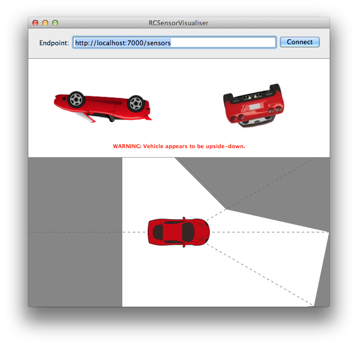
RCSensorVisualizer showing the car’s accelerometer (top) and distance (bottom) sensor readouts graphically.
-
The
CarEventLoopclass runs a dual loop for running AI code. The first loop is a low-latency loop that monitors the car’s sensors, which can have interrupt handlers attached to it — simple classes that decide if execution should be halted, for example if the car turns upside-down. The second loop runs on a different thread and is where the main AI processes will take place. This dual setup allows the car to detect if it’s upside-down and halt operation even an AI process is taking a long time. -
The
I2CUIDeviceclass provides an interface to the screen mounted to the Raspberry Pi, allowing text to be written to the screen and firing events when buttons are pushed. -
The
MenuControllerclass as friends provide logic for presenting a menu system on the display, allowing menu item selection and navigation, as well as “screens” for presenting information or prompting the user to confirm a chosen action.
Bringing It All Together
Below is a video showing the whole lot working together. I scroll through the menus on the Raspberry Pi and observe sensor readouts as well as adjusting the steering and throttle.
The project is now ready for its next steps, which will be writing AI code to have the car navigate its surroundings. It doesn’t have GPS at the moment so it’ll be limited to “drive forwards and don’t crash into stuff” for now, but it’s a start!
You can find the code for this project over on my GitHub. It includes the Arduino Sketch, the C# software stack for the Raspberry Pi and and Objective-C Mac application for observing the sensors.
Shopping List
The project at the moment uses the following hardware:
- 1x Dual Hunter Monster Truck (Tamiya.com).
- 1x Raspberry Pi (RaspberryPi.org).
- 1x Raspberry Pi UI Module with 16x2 LCD (BitWizard.nl).
- 1x Arduino Uno (Arduino.cc).
- 1x Arduino Proto-shield (Arduino.cc).
- 1x ADXL345 Accelerometer (SparkFun.com).
- 4x SRF05 Ultrasonic Sensor (Robot-Electronics.co.uk).
- A ton of wires and stuff to link them all together.