A month or so ago, I wrote a post detailing how I put together an Arduino Mega 2560, a couple of chips and a pile of wires to allow me to control the colour of a set of IKEA Dioder RGB LED strips in software, then a follow-up post on how to emulate Philips’ Ambilight technology to create a pleasing ambient light effect behind your computer’s display.
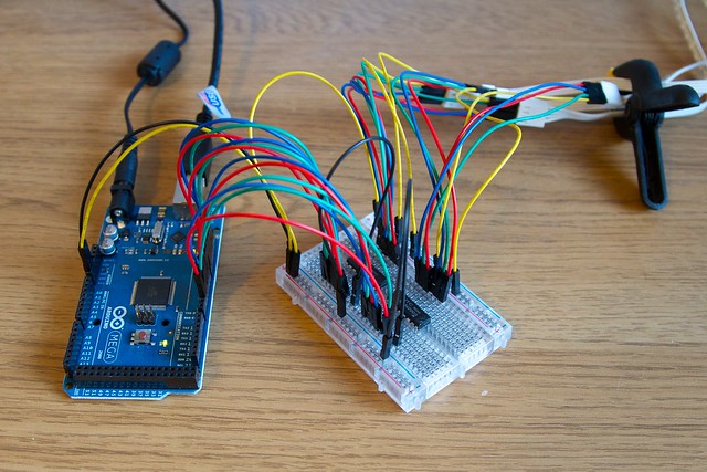
Today, we’ll be tidying up the hardware side of the project from the current sprawling mess of wires:
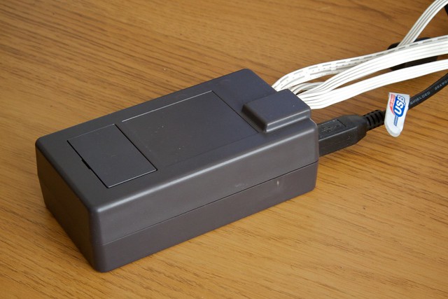
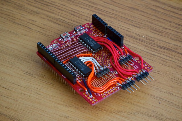
To a neat little box:
Creating an Arduino Shield for DIODER LED Strips
An Arduino shield is a circuit board that connects to an Arduino and contains a certain number of electrical components that perform a certain task — you can buy pre-made shields to give your Arduino an ethernet port, a display, and so on. We’re going to make a shield that stacks on top of the Arduino Mega 2560 and you can connect the LED strips to.
On top of the things you already have, you’ll need the following (Links to Swedish store):
- Soldering Equipment. If you haven’t soldered electronics before, get a strip board and some spare components like resistors to practice with first.
- Assorted lengths of wire. Link] [Real Link
- 1x Box for Arduino. Link
- 1x Proto-Shield for Arduino that includes stacking components. Link
- 16x Right-Angled Strip Headers Link
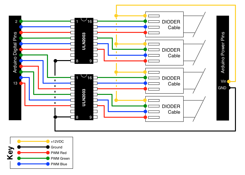
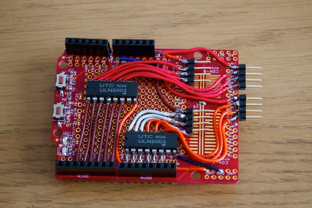
Rather than step you through creating the board, I’ll simply leave you with the circuit diagram to implement and some photos of my finished board.
A few notes:
- You’ll notice that the circuit diagram is a bit different to the one originally presented in the first part of this series. This is to make creating a circuit board easier, and I’ve gone back and updated both the original post and the code on GitHub for this new layout.
- You can probably make your board look way neater than mine!
- The connector pins for the LEDs are right-angled because there’s not enough space in the box for vertical pins and the LED connectors. Angle the two sets of pins that aren’t hanging off the board upwards slightly to make connection easier.
- You can download a PDF of the diagram here.
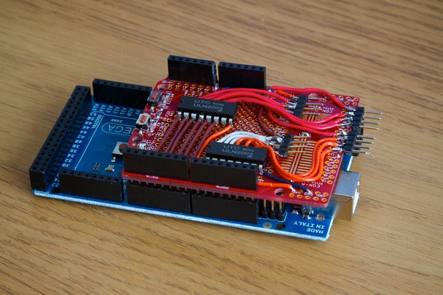
Once you’re completed the board, it will stack on top of the Arduino Mega just fine. Cop a bit out of the box to allow the Dioder cables through, and you’re set!
Moving Forward
As before, let me know on Twitter if you’d like to share and thoughts or idea about this project. Now we have a nice, neat box, in a couple of weeks I’ll post the final part of this series — a System Preference pane with accompanying service to let the lights respond to various system events, falling back to the ambient lighting when nothing else is happening. After that, I’ll take a bit of a break before starting the next, more ambitious, Arduino project.
Have fun!