A couple of weeks ago, I wrote a post detailing the process of combining a set of colour-changing IKEA LED strips, an Arduino, a few simple electronic components and a lot of nerdiness into a project that allowed you to control the colour of the LEDs though a simple application running on your computer.
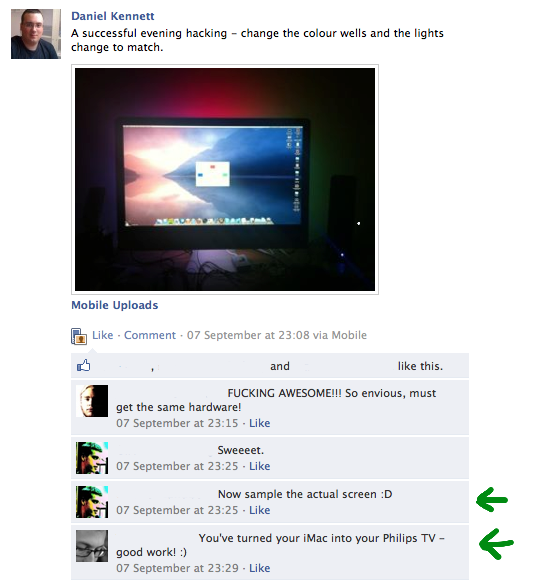
Over the coming weeks and months, I’ll be presenting cool things you can do with this project here on my blog. However, I wasplanning on working up to this post, but since lots of people were enthusiastic about this particular part (as can be seen from the screenshot of my Facebook stream to the right), I jumped ahead a bit.
Now, Philips have a very similar system in a lot of their TVs, and as a colleague at work who called me “Mr. Patent Infringer” pointed out, they probably have a buttload of patents covering their technology.
So, please allow me to present…
An Ambient Lighting Solution Similar To But Legally Distinct From Philips® Ambilight®
So, what’s the challenge here? Well, actually, the core challenge is pretty damn simple:
- Sample the screen.
- Push an appropriate colour based on the edges of the screen image to the lights.
Philips’ hardware also does a fuckton of image processing to smoothly animate between colours and even provides an “aggressiveness” setting to control how sensitive the LEDs are to colour change. I’ll be leaving this as an exercise to the reader for now.
As always, all the code is available at the project’s home on GitHub.
First Attempt: Who let *him* near a computer?
So, I’m not going to lie — my first attempt at this, was, well, lame. For a start, I learned that if you leak a screen’s worth of pixel data every time the screen refreshes (that’s 2560 x 1440 x 4 bytes = just over 14Mb per frame at up to 60Hz), things go very bad very quickly. Once that was fixed, my technique was:
- Register for screen update callbacks using
CGRegisterScreenRefreshCallback(). - Every time I got one of those, render the entire screen image into a new buffer.
- Loop through allof the pixels in the top, bottom, left and right 1/4 rectangles of the image buffer.
- Average the RGB values therein.
- Push those to the Arduino.
As you might imagine, that method is rather inefficient. In fact, it’s downright idiotic, and took nearly 60% of my CPU all the time.
As the implementation matured, various optimisations of course took
place — only an idiot would allocate a new buffer each time the image
changes, for instance. In addition, the
CGRegisterScreenRefreshCallback() callback looks like this:
void screenDidUpdate(CGRectCount count, const CGRect *rectArray, void
*userParameter);
Which provides a lovely rect array telling you which parts of the screen image changed, which is perfect since we only care about parts of the image.
Final Attempt: Passable, I guess
As I attempted to improve the efficiency of the project, I tried only sampling every fourth pixel, scaling the image down, etc, since we obviously don’t need every single pixel sampled to get a single average colour that’s good enough for the lights. However, the very act of rendering the screenshot into a pixel buffer was by far the most intensive part of the whole thing. I was publicly fishing for help on Twitter when @uliwitness reminded me that Core Image exists.
A few minutes later, I’d replaced 90% of my code with a call to a Core Image Filter called CIAreaAverage, which calculates the average colour of a given image. Since Core Image is badass and much better than me, this actually causes all the work to be kept on the graphics card and caused CPU usage to tumble.
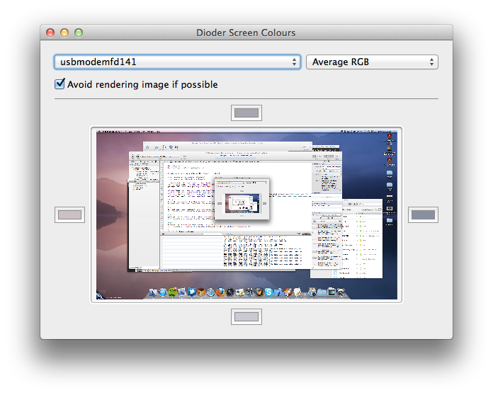
The final project for this post contains two methods of calculating colours:
Pick A Pixel: Literally pick a single pixel near each edge of the screen and use that. Not very clever.
Average RGB: Use Core Image to calculate the average colour of the edge rectangles of the scree as discussed above.
I was also planning on doing an Average Hue method too, since I was expecting Average RGB to give brown every time (possibly a side-effect of always getting shades of brown when mixing colours in art at school). However, Average RGB works just fine so I never implemented it.
Project Status
As of now (commit b3a1b17c038458d498d551a18d120435daf9f778), the project has undergone a few improvements since Part 1 of this series:
- Removed AMSerialPort for my own DKSerialPort class. AMSerialPort was buggy and didn’t work with connection speeds over 9600 baud. DKSerialPort is also a lot smaller.
- Created a class called ArduinoDioderCommunicationController, which abstracts away all the work of communicating with the Arduino running the included sketch. This allows future projects in this series (and you, of course) to drop in the class and just push colours without caring about how it all works.
Of course, I have to include a video of this project in action. The colour changing is a little crappy since I don’t do any smoothing, and unfortunately my camera picked up an odd flickering which isn’t visible by the naked eye, but you get the idea:
Moving Forward
As before, let me know on Twitter if you’d like to share and thoughts or idea about this project. In a week or two I’ll put up another post discussing some more code to make the LED strips respond to system events and so on.
I hope this is enough to get you started, though. Have fun!