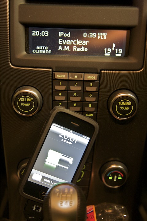
A while ago, I was having signal problems with my iPhone, and wrote about it in my post “How to fix a retarded iPhone with masking tape”. Since then, I’ve replaced it with an iPhone 3G. Much to my (and lots of other people’s) annoyance, the iPhone 3G no longer supports charging on the 12V power pins in the dock cable - only the 5V USB ones. This is a problem when I want to use my C30’s built-in iPod connection - it’ll still allow access to the iPhone’s music through the stereo menu, but it’s pretty useless ‘cause I’ll end up with a flat battery.
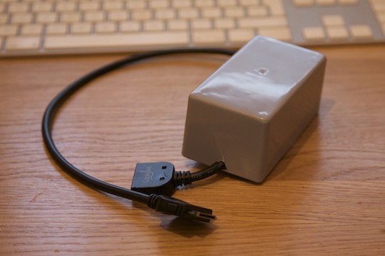
So! Time to make something that fixes the problem. Unfortunately, the iPhone is really pernickety about charging - you can’t just give it 5V over the USB power pins - it needs the voltages on the USB data pins that’d be present on a high-speed USB bus before it accepts the charge. This is the finished product:
Important Information
First, be VERY VERY CAREFUL. You’re messing with electronics that supply a very expensive phone from a probably very expensive car! Shorts will damage your device - my iPod nano no longer charges over USB because I decided to see what happened when you put 12V up the 5V USB power pin.
Second, someone is coming out with a better product than this fairly soon - this is just here for interest’s sake. For instance, the device made below kicks out quite a lot of heat due to the voltage regulator used, and is quite bulky because of the heat sink used. If you still want to go ahead, read on…
What You’ll Need
- Soldering iron, solder and at least some skill with soldering small electronics
- Strip board with at least six lanes
- 1 x 12v -> 5v voltage regulator with heatsink (marked CH35 on the diagram below)
- 2 x 50kohm resistor
- 1 x 150kohm resistor
- 1 x 100kohm resistor
- Thin wire in black and red
- Heat shrink (I used electrical tape, but heat shrink is better)
- A project box to put it all in
- An iPod dock extension cable
- A multimeter for testing
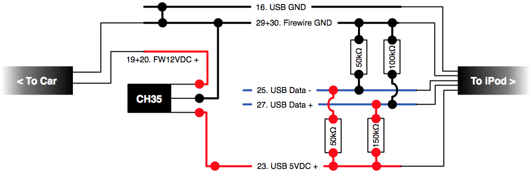
Circuit Diagram
Below is a diagram of what we’ll be doing - pulling the 12V feed from the dock extension cable, regulating it down to 5V and injecting it down the 5V USB feed. At the same time, the USB D+/- feeds will be bridged to the 5V+ and ground feeds to simulate the voltages of a USB high speed bus to make the iPhone pick up the charge. Click for a much bigger and clearer version.
Extracting The Feeds
The first thing we need to do is find and extract the needed feeds from the dock extension cable, while keeping the rest of the feeds intact to preserve the quality of the data and audio going through the cable. First, strip a few inches of sheathing from the cable at your desired location.
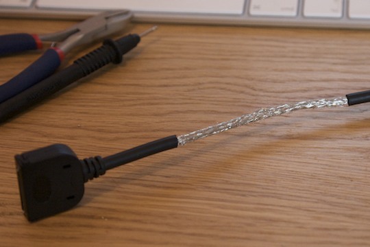
Next, cut a slit along the braiding that surrounds the inner feeds and leave a couple of centimetres at each end twisted up - we’ll join them back together with a wire later.
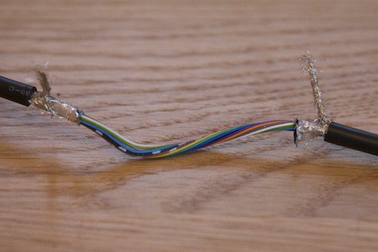
Next, we need to find the feeds we need to work with. Visit the iPod Dock Connector pinouts reference on pinouts.ru and study it carefully. The numbers on my diagram above refer to the pin numbers in that document. Take the cover off the female connector on your extension wire and carefully study the colours of the wires, using a multimeter to check the voltages. Here are the colours of the wires in my cable, but DO NOT copy these - they’ll most probably be different in your cable.
- Dark Blue: 29+30. Firewire Ground
- Brown: 19+20. Firewire +12VDC
- Black: 16. USB ground
- Brown with white stripes: 23. USB +5VDC
- Black with white stripes: 27. USB Data+
- Light green: 25. USB Data-
Cut the Firewire ground and Firewire +12VDC wires at the iPod end of the cable, so you have two long wires coming from the car end. Cut the rest of the needed wires (all those listed above) at the car end, giving long wires coming from the iPod end. This gives you essentially double the length of sheathing you stripped to work with, which’ll make things lots easier!
Putting it all Together
After a few test runs (pushing the components onto your strip board) double and triple-checking your design, solder the components into place. Once done, connect the two braiding stubs we cut off earlier with a black wire - this is an important grounding wire, and needs to be electrically sound. Once done, you should have something like this:
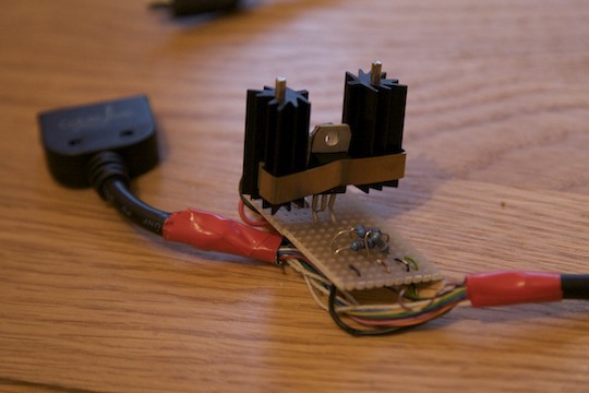
Please Note that it is very important that you have an adequate heat sink in place if you’re using a similar voltage regulator to the one I have here. These things kick out a lot of heat. If the regulator overheats, you’ll hear the audio from the iPhone go very distorted as it starts sending 12V down the 5V line. PROVIDE ADEQUATE COOLING!!!
Finishing Off
Before you connect your modded cable to your computer or your car, find a Firewire->Dock cable, connect your cable to it and use a multimeter to verify the correct voltages are being send up the cable to the iPod. Compared to ground, the voltages should be:
- USB +5VDC: ~+5V
- USB Data+: ~+2V
- USB Data-: s~+2.5V
Once you’ve verified the voltages are correct, connect an iPod to the iPod end of your cable. It should charge. Finally, go down to your car and check it works there - the iPhone should charge and still work with any integration features. If it doesn’t, disconnect it immediately and check your design. Now it works, package it up inside the project box.
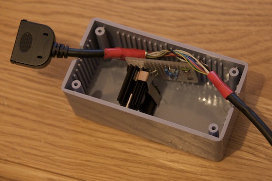
Enjoy your iPhone 3G!